Difference between revisions of "Whole Cerebellum"
| (2 intermediate revisions by 2 users not shown) | |||
| Line 1: | Line 1: | ||
| − | <meta name="title" content="Whole Cerebellum"/> | + | <!-- <meta name="title" content="Whole Cerebellum"/> --> |
{{cer nav}} | {{cer nav}} | ||
__NOTOC__ | __NOTOC__ | ||
| Line 10: | Line 10: | ||
* Paint the cerebellum-brainstem boundary. | * Paint the cerebellum-brainstem boundary. | ||
* Go through and correct topology where needed. | * Go through and correct topology where needed. | ||
| − | + | {{-}} | |
{{h2|Modifying the LUT/Transfer Function}} | {{h2|Modifying the LUT/Transfer Function}} | ||
To open the look-up table (LUT)/Transfer function window, press the button located on the image toolbar in MIPAV [[Image:Lutbutton.PNG]]. If this is not visible, use Toolbars > Image Toolbar to open it. The new window should resemble the image in Figure 1. Also shown below in Figure 2 is an image corresponding to the LUT shown. | To open the look-up table (LUT)/Transfer function window, press the button located on the image toolbar in MIPAV [[Image:Lutbutton.PNG]]. If this is not visible, use Toolbars > Image Toolbar to open it. The new window should resemble the image in Figure 1. Also shown below in Figure 2 is an image corresponding to the LUT shown. | ||
Latest revision as of 00:49, 3 July 2022
| Cerebellum Protocol Project | |||
|---|---|---|---|
| Whole Cerebellum | Lobe Definitions | Vermis Definition | Lobule Delineation |
Whole Cerebellum
Outline
- Modify LUT/transfer function to improve contrast.
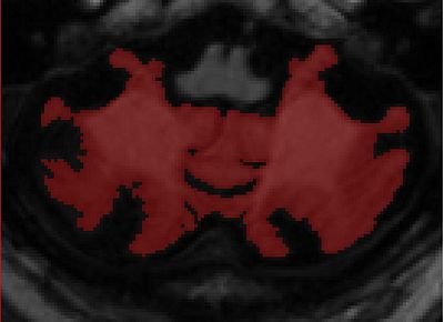
- Use the threshold tool to approximate cerebellum-csf boundary.
- Paint the cerebellum-brainstem boundary.
- Go through and correct topology where needed.
Modifying the LUT/Transfer Function
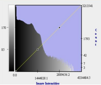
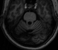
To open the look-up table (LUT)/Transfer function window, press the button located on the image toolbar in MIPAV . If this is not visible, use Toolbars > Image Toolbar to open it. The new window should resemble the image in Figure 1. Also shown below in Figure 2 is an image corresponding to the LUT shown.
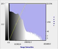
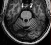
To increase the contrast, making the cerebellar structures more easily appreciated, modify the yellow line to resemble the one shown below. Note the improved contrast in the corresponding image.
The LUT is a histogram of the pixel intensities.
This button does something similar: ![]() just click and drag. You can always readjust using the LUT.
just click and drag. You can always readjust using the LUT.
When adjusting the LUT try several different settings to be sure you pick the best, but also try to be consistent. We want our ratings to be as accurate as possible so try to set the LUT in the same manner for every image.
Adjusting the Threshold Tool
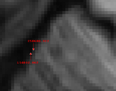
To find the intensity values that most closely match the pixels at the CSF (cerebral spinal fluid) -cerebellum boundary, first select the pointer cursor . Then, find the intensity at a pixel you would like to include as part of the delineation by clicking with the pointer. Next, find the intensity at a pixel that you would like to exclude from the delineation. Determine the average of those two intensities and make that your threshold value. See example below. It is a good idea to set several thresholds and test each in several areas of the scan and with several different levels of contrast. Do this to be sure you make the right choice and to help you be consistent with your choices.
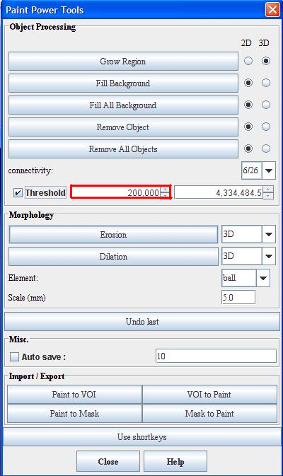
In this example, we start with a threshold of 200,000. Next, open powerpaint tools with the button . This will open a window resembling the figure below. Type in the appropriate threshold in the field indicated by the red border and check the threshold option as shown.
Painting With the Threshold
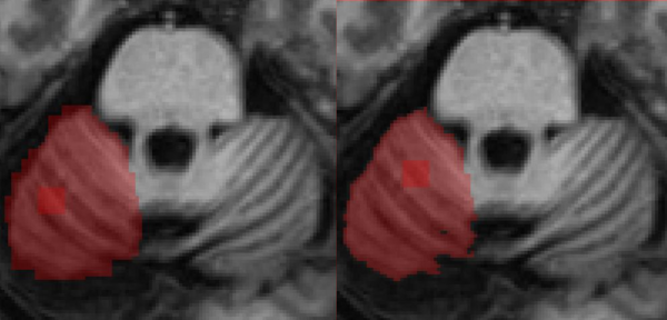
Select the paintbrush and paint in the cerebellum. Left click to paint right click to erase. You will notice that pixels with intensities below your threshold will not be painted. It is important to remember that the first stroke painted will not register the threshold. If it is still not working, try clicking the up and down arrows next to the threshold box, then try again. Use a large paintbrush (e.g. 8x8 or 10x10). The figure below shows the painted area before and after thresholding. You need to test/adjust the threshold value for a couple slides to find the "best" number. A lower threshold is preferable to reduce “holes” in the painted region and to ensure that all cerebellar gray matter is included.
Note: The threshold is a little temperamental; it may or may not change immediately. Try multiple different settings.
It is also possible to paint using the threshold in the tri-planar window. This is a series of steps that I have taken that has worked in the past and may or may not work in the version of MIPAV you are using.
Open the MRI scan first. Then load the advanced paint tools. Now open the Tri-planar view. Next load the power paint tools. Enter your threshold and check the box. Test it at least twice in the original image and then, if it works, try it in the tri-planar. If it doesn't work check and uncheck it again and test it twice more in the original and once in the tri-planar.
Note: The threshold will no longer work if the paintbrush is not selected in the original image. In addition when painting do not close the advanced paint tools window, if you do open it again. When the advanced paint tools window is closed it makes everything into masks.
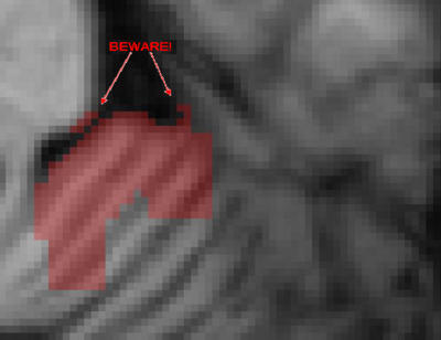
Caution! : When doing this be careful not to paint regions outside the cerebellum. It is quite easy to paint high-intensity regions outside of the cerebellum. This is especially true where the cerebellum touches the cortex. The best way to define the boundary between the cerebellum and the cortex is to consider the texture of the image. This texture difference results from the lower spatial frequency and distinct orientation of cortical folds relative to the cerebellar folia.
Painting the Cerebellum-Brainstem Boundary
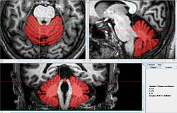
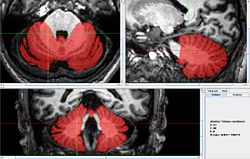
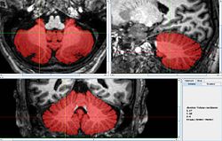
It is now that extra care should be taken to ensure that the Cerebellum-Brainstem boundary is correctly painted. Use a smaller brush for this (4x4 or 3x3 recommended). Open the tri-planar view .
These are the steps to accurately draw the Cerebellum-Brainstem boundary:
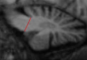
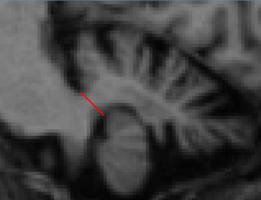
- In any given saggital slice, consider the superior portion of the cerebellum. Locate the anterior most GM-WM-CSF (grey matter, white matter, cerebral spinal fluid) interface.
- Repeat (1) considering the inferior portion of the cerebellum. (be sure not to forget about Lob. X – flocculi)
- The line joining these two points forms the cerebellum-brainstem boundary in this slice.
- Always maintain a qualitative degree of smoothness between the corpus medullare and brainstem (check adjacent slices and orthogonal views).
Final Review
After completing the above, it is recommended to review the entire cerebellum in the sagittal view. Most likely, there will be many artifacts present in the delineation, especially stray unpainted pixels (“holes”). These must be manually corrected. You should revise the Cerebellum/CSF boundary where appropriate. HINT: To keep using the threshold in this view, one must return to the primary axial view and click anywhere on the outside of the brain. This will apply the threshold retroactively to all the slides.
